
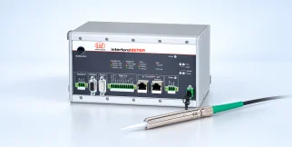
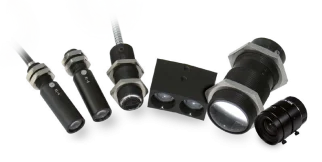















optoNCDT 1420 Laser triangulation
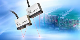
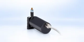
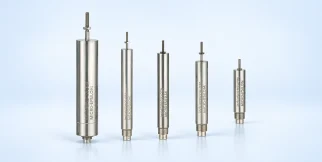
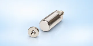
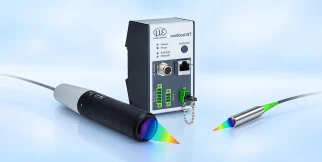
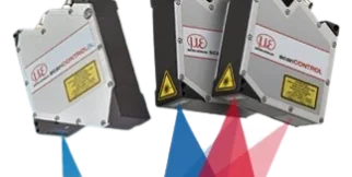
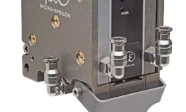
optoNCDT 1420: sensors and measurement devices by Micro-Epsilon for laser triangulation.
Download the datasheet (opens in a new tab) This series on the Micro-Epsilon site (opens in a new tab)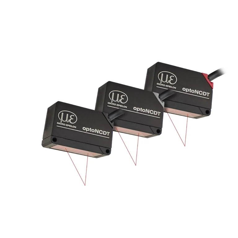
Shared technical specifications for the series
Properties every model in the series has. What differs is in the models table below.
Range across models
The span covered by the models of the series together — not the range of each model.
| Light spot width X | 0.045–0.71 mm |
|---|---|
| Selectable measuring rates | 250–4000 Hz |
| Linearity | 8–1000 µm |
| Measuring rate | 2000–8000 Hz |
| Light spot width Y | 0.05–0.91 mm |
| Start of measuring range | 20–100 mm |
| Measuring range | 10–500 mm |
| Repeatability | 0.5–40 µm |
| End of measuring range | 30–600 mm |
| Working distance | 20–600 mm |
| Accuracy | 8–1000 µm |
Models in the series
One column per model: what differs between the models of the series.
| Parameter | ILD1420-10 | ILD1420-10 — Integrated cable 3 m, open ends | ILD1420-10 — Pigtail 0.3 m, M12 12-pin | ILD1420-100 | ILD1420-100 — Integrated cable 3 m, open ends | ILD1420-100 — Pigtail 0.3 m, M12 12-pin | ILD1420-200 | ILD1420-200 — Integrated cable 3 m, open ends | ILD1420-200 — Pigtail 0.3 m, M12 12-pin | ILD1420-25 | ILD1420-25 — Integrated cable 3 m, open ends | ILD1420-25 — Pigtail 0.3 m, M12 12-pin | ILD1420-50 | ILD1420-50 — Integrated cable 3 m, open ends | ILD1420-50 — Pigtail 0.3 m, M12 12-pin | ILD1420-500 | ILD1420-500 — Integrated cable 3 m, open ends | ILD1420-500 — Pigtail 0.3 m, M12 12-pin |
|---|---|---|---|---|---|---|---|---|---|---|---|---|---|---|---|---|---|---|
| Light spot width X | 0.045 mm | Not specified | Not specified | 0.71 mm | Not specified | Not specified | 0.71 mm | Not specified | Not specified | 0.055 mm | Not specified | Not specified | 0.075 mm | Not specified | Not specified | 0.71 mm | Not specified | Not specified |
| Outputs and interfaces | Analog 0-10V | Not specified | Not specified | RS422 / RS485 | Not specified | Not specified | Analog 0-10V | Not specified | Not specified | Digital I/O | Not specified | Not specified | Analog 0-10V | Not specified | Not specified | Digital I/O | Not specified | Not specified |
| Selectable measuring rates | 250 Hz | Not specified | Not specified | 2 kHz | Not specified | Not specified | 2 kHz | Not specified | Not specified | 1 kHz | Not specified | Not specified | 1 kHz | Not specified | Not specified | 4 kHz | Not specified | Not specified |
| Linearity | 8 µm | 8 µm | 8 µm | 80 µm | 80 µm | 80 µm | 160 µm | 160 µm | 160 µm | 20 µm | 20 µm | 20 µm | 40 µm | 40 µm | 40 µm | 1000 µm | < ±500…1000 µm | < ±500…1000 µm |
| Measuring rate | 2 kHz | 8 kHz | 8 kHz | 2 kHz | 8 kHz | 8 kHz | 2 kHz | 8 kHz | 8 kHz | 2 kHz | 8 kHz | 8 kHz | 2 kHz | 8 kHz | 8 kHz | 2 kHz | 8 kHz | 8 kHz |
| Operating temperature | 0–50 °C | Not specified | Not specified | 0–50 °C | Not specified | Not specified | 0–50 °C | Not specified | Not specified | 0–50 °C | Not specified | Not specified | 0–50 °C | Not specified | Not specified | 0–50 °C | Not specified | Not specified |
| Light spot width Y | 0.05 mm | Not specified | Not specified | 0.91 mm | Not specified | Not specified | 0.91 mm | Not specified | Not specified | 0.06 mm | Not specified | Not specified | 0.095 mm | Not specified | Not specified | 0.91 mm | Not specified | Not specified |
| Start of measuring range | 20 mm | 20 mm | 20 mm | 50 mm | 50 mm | 50 mm | 60 mm | 60 mm | 60 mm | 25 mm | 25 mm | 25 mm | 35 mm | 35 mm | 35 mm | 100 mm | 100 mm | 100 mm |
| Measuring range | 10 mm | 10 mm | 10 mm | 100 mm | 100 mm | 100 mm | 200 mm | 200 mm | 200 mm | 25 mm | 25 mm | 25 mm | 50 mm | 50 mm | 50 mm | 500 mm | 500 mm | 500 mm |
| Protection class (DIN EN 60529) | IP67 | IP67 | IP67 | IP67 | IP67 | IP67 | IP67 | IP67 | IP67 | IP67 | IP67 | IP67 | IP67 | IP67 | IP67 | IP67 | IP67 | IP67 |
| Repeatability | 0.5 µm | 0.5 µm | 0.5 µm | 4 µm | 4 µm | 4 µm | Not specified | 8…16 µm | 8…16 µm | 1 µm | 1 µm | 1 µm | 2 µm | 2 µm | 2 µm | Not specified | 20…40 µm | 20…40 µm |
| End of measuring range | 30 mm | 30 mm | 30 mm | 150 mm | 150 mm | 150 mm | 260 mm | 260 mm | 260 mm | 50 mm | 50 mm | 50 mm | 85 mm | 85 mm | 85 mm | 600 mm | 600 mm | 600 mm |
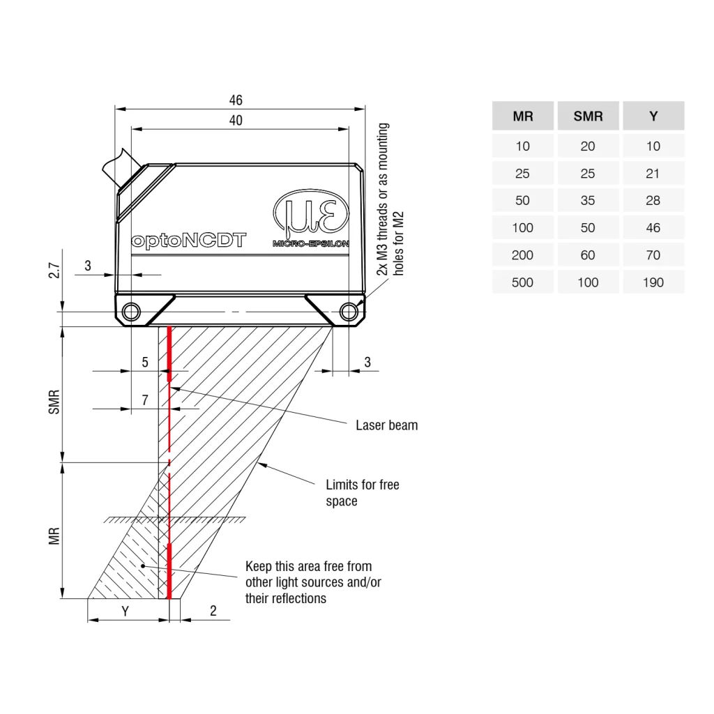
| Working distance | 20–60 mm | Not specified | Not specified | 50–150 mm | Not specified | Not specified | 60–260 mm | Not specified | Not specified | 25–50 mm | Not specified | Not specified | 40–120 mm | Not specified | Not specified | 100–600 mm | Not specified | Not specified |
| Contact | Non-contact | Non-contact | Non-contact | Non-contact | Non-contact | Non-contact | Non-contact | Non-contact | Non-contact | Non-contact | Non-contact | Non-contact | Non-contact | Non-contact | Non-contact | Non-contact | Non-contact | Non-contact |
| Accuracy | 8 µm | Not specified | Not specified | 80 µm | Not specified | Not specified | 160 µm | Not specified | Not specified | 20 µm | Not specified | Not specified | 40 µm | Not specified | Not specified | 1000 µm | Not specified | Not specified |
| ADC sampling rate | 8000 samples/s | Not specified | Not specified | 8000 samples/s | Not specified | Not specified | 8000 samples/s | Not specified | Not specified | 8000 samples/s | Not specified | Not specified | 8000 samples/s | Not specified | Not specified | 8000 samples/s | Not specified | Not specified |
| Interfaces | Not specified | RS422 | RS422 | Ethernet | RS422 | RS422 | Ethernet | RS422 | RS422 | Ethernet | RS422 | RS422 | Not specified | RS422 | RS422 | Ethernet | RS422 | RS422 |
| Technical specification details | Not specified | Not specified | Not specified | 100 mm net measuring range; 50-150 mm sensor-to-target working window. | Not specified | Not specified | 200 mm net measuring range; 60-260 mm sensor-to-target working window. | Not specified | Not specified | 25 mm net measuring range; 25-50 mm sensor-to-target working window. | Not specified | Not specified | Not specified | Not specified | Not specified | 500 mm net measuring range; 100-600 mm sensor-to-target working window. | Not specified | Not specified |
| Status | Active | Active | Active | Active | Active | Active | Active | Active | Active | Active | Active | Active | Active | Active | Active | Active | Active | Active |
| Datasheet | PDF — ILD1420-10 (opens in a new tab) | PDF — ILD1420-10 — Integrated cable 3 m, open ends (opens in a new tab) | PDF — ILD1420-10 — Pigtail 0.3 m, M12 12-pin (opens in a new tab) | PDF — ILD1420-100 (opens in a new tab) | PDF — ILD1420-100 — Integrated cable 3 m, open ends (opens in a new tab) | PDF — ILD1420-100 — Pigtail 0.3 m, M12 12-pin (opens in a new tab) | PDF — ILD1420-200 (opens in a new tab) | PDF — ILD1420-200 — Integrated cable 3 m, open ends (opens in a new tab) | PDF — ILD1420-200 — Pigtail 0.3 m, M12 12-pin (opens in a new tab) | PDF — ILD1420-25 (opens in a new tab) | PDF — ILD1420-25 — Integrated cable 3 m, open ends (opens in a new tab) | PDF — ILD1420-25 — Pigtail 0.3 m, M12 12-pin (opens in a new tab) | PDF — ILD1420-50 (opens in a new tab) | PDF — ILD1420-50 — Integrated cable 3 m, open ends (opens in a new tab) | PDF — ILD1420-50 — Pigtail 0.3 m, M12 12-pin (opens in a new tab) | PDF — ILD1420-500 (opens in a new tab) | PDF — ILD1420-500 — Integrated cable 3 m, open ends (opens in a new tab) | PDF — ILD1420-500 — Pigtail 0.3 m, M12 12-pin (opens in a new tab) |
The industries we serve
-
-
Aerospace
- Aircraft door-lock position detection
- Airlines & Aerospace Our balancing machines and moment weighing scales for aerospace drives ensure maximum precision, ease of use, and modular flexibility delivering reliability and performance without compromise contributing to your economic success.
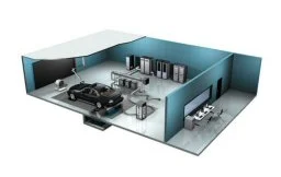
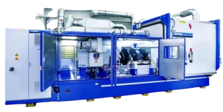
- Automatic balancing machines Automatic balancing machines from Schenck are advanced solutions for precise balancing of rotating components in automated production processes. We offer systems and stations for balancing crankshafts, wheels and tires, turbochargers, electric armatures, drives, axle drive units, torque converters, drive shafts, disc-shaped rotors, as well as fans. Our systems increase productivity, ensure consistent quality, and are tailored to the needs of the automotive, energy, and industrial sectors.
-
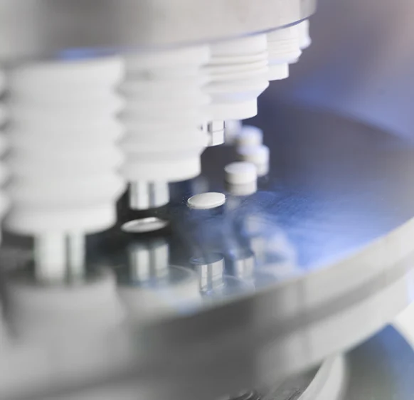
Medical industry
-
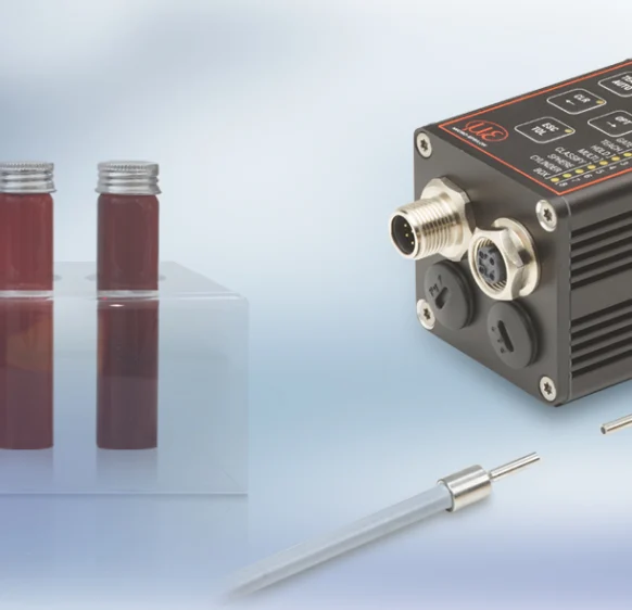
Environment
-
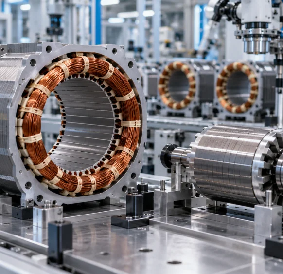
Electric motor manufacturing
-
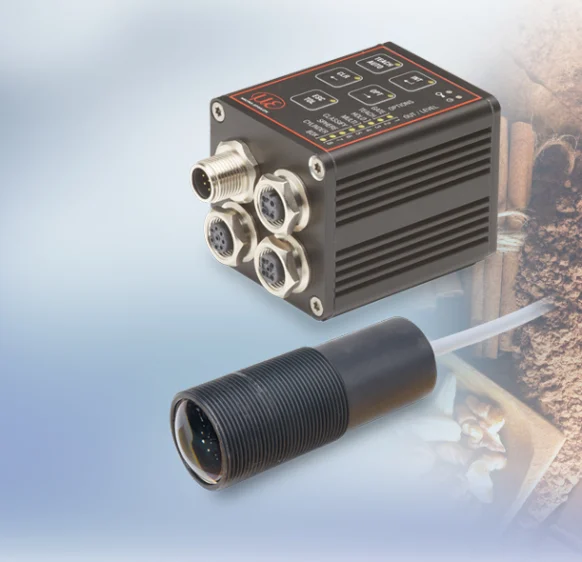
Food industry
-
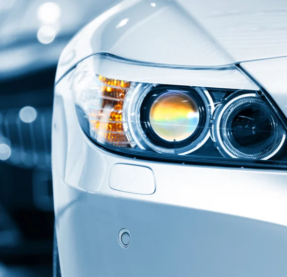
Automotive industry
- Airlines & Aerospace Our balancing machines and moment weighing scales for aerospace drives ensure maximum precision, ease of use, and modular flexibility delivering reliability and performance without compromise contributing to your economic success.
- Automatic balancing machines Automatic balancing machines from Schenck are advanced solutions for precise balancing of rotating components in automated production processes. We offer systems and stations for balancing crankshafts, wheels and tires, turbochargers, electric armatures, drives, axle drive units, torque converters, drive shafts, disc-shaped rotors, as well as fans. Our systems increase productivity, ensure consistent quality, and are tailored to the needs of the automotive, energy, and industrial sectors.
- Axle Drives With our balancing machines for front and rear axle transmissions, the measured unbalance is corrected by drilling into the drive flanges of the transmissions (welding optional). We support you with our interdisciplinary expertise in the production of front and rear axle transmissions from the initial idea to the design stage through to series production.
-
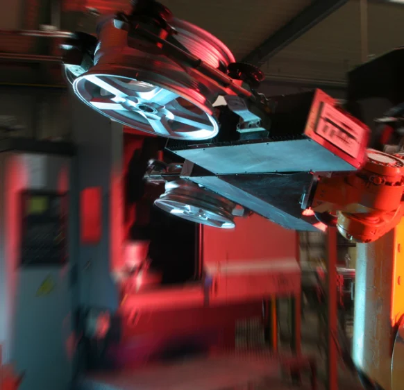
Industrial automation
-
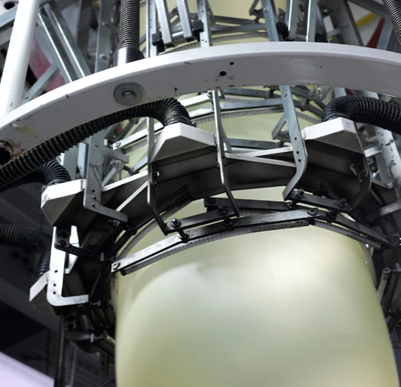
Plastics
-
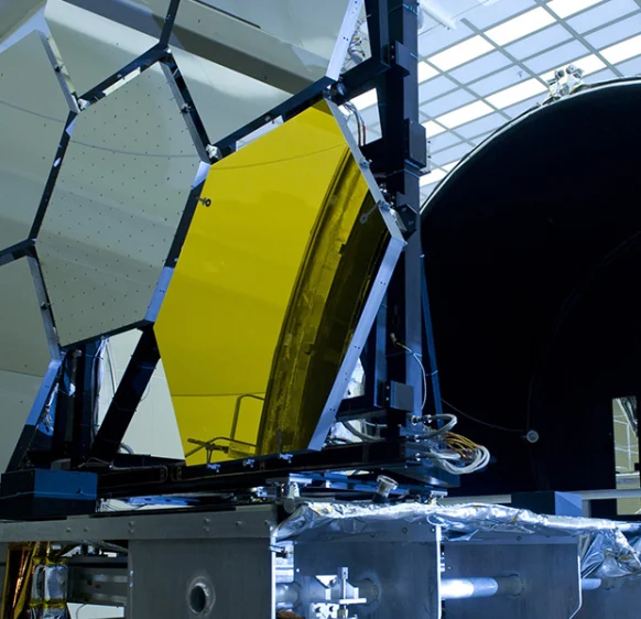
Optics
-
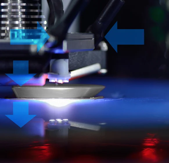
3D printing
-
Battery manufacturing
Frequently asked questions
Answers to the most common questions about our products and services
No. Class 2 specifies up to 8 kHz versus a 2 kHz factory setting. Catalogue footnotes limit Class 1 to 4 kHz. The operating rate must also suit the surface and exposure.
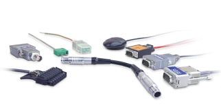
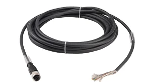
The manufacturer lists a 0.3 m pigtail with an M12 connector and a 3 m integrated sensor cable with open ends. Select the correct variant; the connector drawing does not describe the open-ended cable termination.
Yes. Catalogue footnotes limit Class 1 to 4 kHz, specify IP65 and 12-bit analog conversion. Do not automatically apply the Class 2 specifications.
No. The catalogue identifies PCF1420-3/U for 1–5 V output alongside current configurations. Match the cable to head variant and required output.
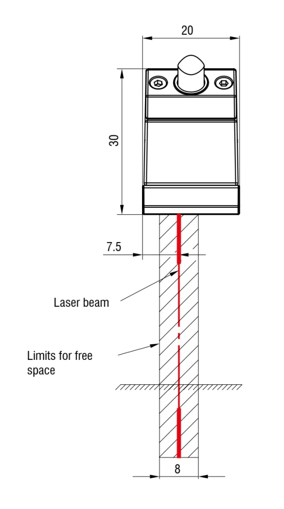
Check both light-spot dimensions at the working position. The smallest spot may occur at a specific distance and is not uniform over the span.
Get a quote or advice
Tell us what you need and an engineer will come back to you.
Request a quote for this product