
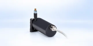
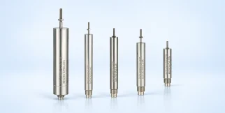
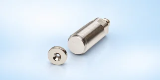
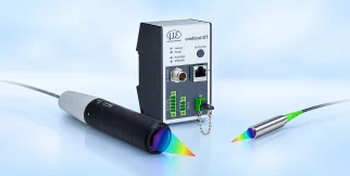
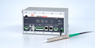
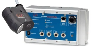
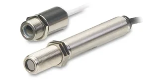
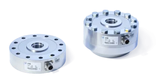












wireSENSOR P60
wireSENSOR P60: sensors and measurement devices by Micro-Epsilon for distance & displacement sensors.
Download the datasheet (opens in a new tab) This series on the Micro-Epsilon site (opens in a new tab)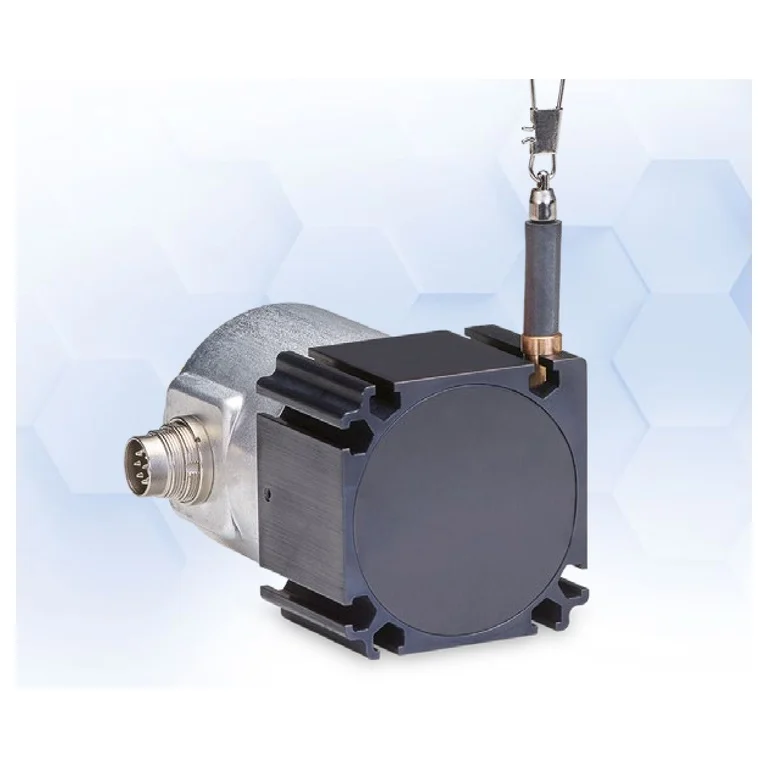
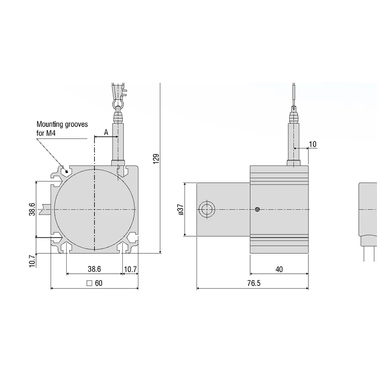
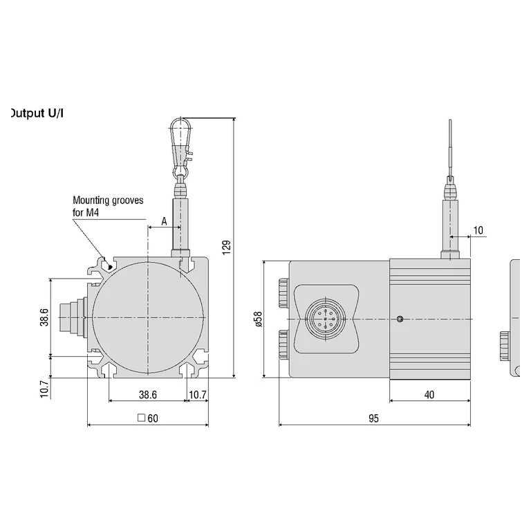
Shared technical specifications for the series
Properties every model in the series has. What differs is in the models table below.
Range across models
The span covered by the models of the series together — not the range of each model.
| Measuring range | 100–1500 mm |
|---|---|
| Linearity (% FSO) | 0.02–0.5 % |
| Linearity | 200–1500 µm |
| Output resolution (length) | 12–100 µm |
Models in the series
One column per model: what differs between the models of the series.
| Parameter | WDS-100-P60-CR-P | WDS-100-P60-SR-I | WDS-100-P60-SR-U | WDS-1000-P60-BH-CAT | WDS-1000-P60-BH-CO | WDS-1000-P60-BH-ENIP | WDS-1000-P60-BH-PB | WDS-1000-P60-BH-PN | WDS-1000-P60-CR-HTL | WDS-1000-P60-CR-P | WDS-1000-P60-CR-TTL | WDS-1000-P60-SR-I | WDS-1000-P60-SR-SSI | WDS-1000-P60-SR-U | WDS-150-P60-CR-P | WDS-150-P60-SR-I | WDS-150-P60-SR-U | WDS-1500-P60-BH-CAT | WDS-1500-P60-BH-CO | WDS-1500-P60-BH-ENIP | WDS-1500-P60-BH-PB | WDS-1500-P60-BH-PN | WDS-1500-P60-CR-HTL | WDS-1500-P60-CR-P | WDS-1500-P60-CR-TTL | WDS-1500-P60-SR-I | WDS-1500-P60-SR-SSI | WDS-1500-P60-SR-U | WDS-300-P60-CR-P | WDS-300-P60-SR-I | WDS-300-P60-SR-U | WDS-500-P60-CR-P | WDS-500-P60-SR-I | WDS-500-P60-SR-U | WDS-750-P60-CR-P | WDS-750-P60-SR-I | WDS-750-P60-SR-U |
|---|---|---|---|---|---|---|---|---|---|---|---|---|---|---|---|---|---|---|---|---|---|---|---|---|---|---|---|---|---|---|---|---|---|---|---|---|---|
| Measuring range | 100 mm | 100 mm | 100 mm | 1000 mm | 1000 mm | 1000 mm | 1000 mm | 1000 mm | 1000 mm | 1000 mm | 1000 mm | 1000 mm | 1000 mm | 1000 mm | 150 mm | 150 mm | 150 mm | 1500 mm | 1500 mm | 1500 mm | 1500 mm | 1500 mm | 1500 mm | 1500 mm | 1500 mm | 1500 mm | 1500 mm | 1500 mm | 300 mm | 300 mm | 300 mm | 500 mm | 500 mm | 500 mm | 750 mm | 750 mm | 750 mm |
| Selected electrical output | Potentiometer / resistance divider | Analog current | Analog voltage | EtherCAT | CANopen | EtherNet/IP | Profibus DP | PROFINET | HTL | Potentiometer / resistance divider | TTL | Analog current | SSI Gray code | Analog voltage | Potentiometer / resistance divider | Analog current | Analog voltage | EtherCAT | CANopen | EtherNet/IP | Profibus DP | PROFINET | HTL | Potentiometer / resistance divider | TTL | Analog current | SSI Gray code | Analog voltage | Potentiometer / resistance divider | Analog current | Analog voltage | Potentiometer / resistance divider | Analog current | Analog voltage | Potentiometer / resistance divider | Analog current | Analog voltage |
| Selected configuration options | range=100 mm; suffix=CR-P; output=Potentiometer / resistance divider | range=100 mm; suffix=SR-I; output=Analog current | range=100 mm; suffix=SR-U; output=Analog voltage | range=1000 mm; suffix=BH-CAT; output=EtherCAT | range=1000 mm; suffix=BH-CO; output=CANopen | range=1000 mm; suffix=BH-ENIP; output=EtherNet/IP | range=1000 mm; suffix=BH-PB; output=Profibus DP | range=1000 mm; suffix=BH-PN; output=PROFINET | range=1000 mm; suffix=CR-HTL; output=HTL | range=1000 mm; suffix=CR-P; output=Potentiometer / resistance divider | range=1000 mm; suffix=CR-TTL; output=TTL | range=1000 mm; suffix=SR-I; output=Analog current | range=1000 mm; suffix=SR-SSI; output=SSI Gray code | range=1000 mm; suffix=SR-U; output=Analog voltage | range=150 mm; suffix=CR-P; output=Potentiometer / resistance divider | range=150 mm; suffix=SR-I; output=Analog current | range=150 mm; suffix=SR-U; output=Analog voltage | range=1500 mm; suffix=BH-CAT; output=EtherCAT | range=1500 mm; suffix=BH-CO; output=CANopen | range=1500 mm; suffix=BH-ENIP; output=EtherNet/IP | range=1500 mm; suffix=BH-PB; output=Profibus DP | range=1500 mm; suffix=BH-PN; output=PROFINET | range=1500 mm; suffix=CR-HTL; output=HTL | range=1500 mm; suffix=CR-P; output=Potentiometer / resistance divider | range=1500 mm; suffix=CR-TTL; output=TTL | range=1500 mm; suffix=SR-I; output=Analog current | range=1500 mm; suffix=SR-SSI; output=SSI Gray code | range=1500 mm; suffix=SR-U; output=Analog voltage | range=300 mm; suffix=CR-P; output=Potentiometer / resistance divider | range=300 mm; suffix=SR-I; output=Analog current | range=300 mm; suffix=SR-U; output=Analog voltage | range=500 mm; suffix=CR-P; output=Potentiometer / resistance divider | range=500 mm; suffix=SR-I; output=Analog current | range=500 mm; suffix=SR-U; output=Analog voltage | range=750 mm; suffix=CR-P; output=Potentiometer / resistance divider | range=750 mm; suffix=SR-I; output=Analog current | range=750 mm; suffix=SR-U; output=Analog voltage |
| Selected connection | Integrated cable, radial, 1 m | 8-pin flange connector DIN45326, radial | 8-pin flange connector DIN45326, radial | Bus cover; connector depends on selected protocol | Bus cover; connector depends on selected protocol | Bus cover; connector depends on selected protocol | Bus cover; connector depends on selected protocol | Bus cover; connector depends on selected protocol | Integrated cable, radial, 1 m | Integrated cable, radial, 1 m | Integrated cable, radial, 1 m | 8-pin flange connector DIN45326, radial | 12-pin flange connector, radial | 8-pin flange connector DIN45326, radial | Integrated cable, radial, 1 m | 8-pin flange connector DIN45326, radial | 8-pin flange connector DIN45326, radial | Bus cover; connector depends on selected protocol | Bus cover; connector depends on selected protocol | Bus cover; connector depends on selected protocol | Bus cover; connector depends on selected protocol | Bus cover; connector depends on selected protocol | Integrated cable, radial, 1 m | Integrated cable, radial, 1 m | Integrated cable, radial, 1 m | 8-pin flange connector DIN45326, radial | 12-pin flange connector, radial | 8-pin flange connector DIN45326, radial | Integrated cable, radial, 1 m | 8-pin flange connector DIN45326, radial | 8-pin flange connector DIN45326, radial | Integrated cable, radial, 1 m | 8-pin flange connector DIN45326, radial | 8-pin flange connector DIN45326, radial | Integrated cable, radial, 1 m | 8-pin flange connector DIN45326, radial | 8-pin flange connector DIN45326, radial |
| Protection class (DIN EN 60529) | IP65 | IP65; For plug versions only when connected | IP65; For plug versions only when connected | IP65; For plug versions only when connected | IP65; For plug versions only when connected | IP65; For plug versions only when connected | IP65; For plug versions only when connected | IP65; For plug versions only when connected | IP65 | IP65 | IP65 | IP65; For plug versions only when connected | IP65; For plug versions only when connected | IP65; For plug versions only when connected | IP65 | IP65; For plug versions only when connected | IP65; For plug versions only when connected | IP65; For plug versions only when connected | IP65; For plug versions only when connected | IP65; For plug versions only when connected | IP65; For plug versions only when connected | IP65; For plug versions only when connected | IP65 | IP65 | IP65 | IP65; For plug versions only when connected | IP65; For plug versions only when connected | IP65; For plug versions only when connected | IP65 | IP65; For plug versions only when connected | IP65; For plug versions only when connected | IP65 | IP65; For plug versions only when connected | IP65; For plug versions only when connected | IP65 | IP65; For plug versions only when connected | IP65; For plug versions only when connected |
| Linearity (% FSO) | 0.5 % | 0.5 % | 0.5 % | 0.02 % | 0.02 % | 0.02 % | 0.02 % | 0.02 % | 0.02 % | 0.1 % | 0.02 % | 0.1 % | 0.02 % | 0.1 % | 0.5 % | 0.5 % | 0.5 % | 0.02 % | 0.02 % | 0.02 % | 0.02 % | 0.02 % | 0.02 % | 0.1 % | 0.02 % | 0.1 % | 0.02 % | 0.1 % | 0.25 % | 0.25 % | 0.25 % | 0.1 % | 0.1 % | 0.1 % | 0.1 % | 0.1 % | 0.1 % |
| Linearity | 500 µm | 500 µm | 500 µm | 200 µm | 200 µm | 200 µm | 200 µm | 200 µm | 200 µm | 1000 µm | 200 µm | 1000 µm | 200 µm | 1000 µm | 750 µm | 750 µm | 750 µm | 300 µm | 300 µm | 300 µm | 300 µm | 300 µm | 300 µm | 1500 µm | 300 µm | 1500 µm | 300 µm | 1500 µm | 750 µm | 750 µm | 750 µm | 500 µm | 500 µm | 500 µm | 750 µm | 750 µm | 750 µm |
| Mechanical details from model-specific source cells | Resolution: source gives a qualitative potentiometer limit; no numeric zero assigned. | Resolution: source gives a qualitative potentiometer limit; no numeric zero assigned. | Resolution: source gives a qualitative potentiometer limit; no numeric zero assigned. | Wire extension force (max.): approx. 7.5 N; Wire retraction force (min.): approx. 5 N; Wire acceleration (max.): approx. 10 g; Material / Housing: Aluminum; Material / Measuring wire: Polyamide-coated stainless steel (ø 0.45 mm); Wire mounting: Wire clip; Installation: Mounting grooves on the sensor housing; Temperature range / Storage: -20 … +80 °C; Temperature range / Operation: -20 … +80 °C; Shock (DIN EN 60068-2-27): 50 g / 10 ms in 3 axes, 1000 shocks each; Vibration (DIN EN 60068-2-6): 20 g / 10 … 2 kHz in 3 axes, 10 cycles each; Weight: approx. 1 kg | Wire extension force (max.): approx. 7.5 N; Wire retraction force (min.): approx. 5 N; Wire acceleration (max.): approx. 10 g; Material / Housing: Aluminum; Material / Measuring wire: Polyamide-coated stainless steel (ø 0.45 mm); Wire mounting: Wire clip; Installation: Mounting grooves on the sensor housing; Temperature range / Storage: -20 … +80 °C; Temperature range / Operation: -20 … +80 °C; Shock (DIN EN 60068-2-27): 50 g / 10 ms in 3 axes, 1000 shocks each; Vibration (DIN EN 60068-2-6): 20 g / 10 … 2 kHz in 3 axes, 10 cycles each; Weight: approx. 1 kg | Wire extension force (max.): approx. 7.5 N; Wire retraction force (min.): approx. 5 N; Wire acceleration (max.): approx. 10 g; Material / Housing: Aluminum; Material / Measuring wire: Polyamide-coated stainless steel (ø 0.45 mm); Wire mounting: Wire clip; Installation: Mounting grooves on the sensor housing; Temperature range / Storage: -20 … +80 °C; Temperature range / Operation: -20 … +80 °C; Shock (DIN EN 60068-2-27): 50 g / 10 ms in 3 axes, 1000 shocks each; Vibration (DIN EN 60068-2-6): 20 g / 10 … 2 kHz in 3 axes, 10 cycles each; Weight: approx. 1 kg | Wire extension force (max.): approx. 7.5 N; Wire retraction force (min.): approx. 5 N; Wire acceleration (max.): approx. 10 g; Material / Housing: Aluminum; Material / Measuring wire: Polyamide-coated stainless steel (ø 0.45 mm); Wire mounting: Wire clip; Installation: Mounting grooves on the sensor housing; Temperature range / Storage: -20 … +80 °C; Temperature range / Operation: -20 … +80 °C; Shock (DIN EN 60068-2-27): 50 g / 10 ms in 3 axes, 1000 shocks each; Vibration (DIN EN 60068-2-6): 20 g / 10 … 2 kHz in 3 axes, 10 cycles each; Weight: approx. 1 kg | Wire extension force (max.): approx. 7.5 N; Wire retraction force (min.): approx. 5 N; Wire acceleration (max.): approx. 10 g; Material / Housing: Aluminum; Material / Measuring wire: Polyamide-coated stainless steel (ø 0.45 mm); Wire mounting: Wire clip; Installation: Mounting grooves on the sensor housing; Temperature range / Storage: -20 … +80 °C; Temperature range / Operation: -20 … +80 °C; Shock (DIN EN 60068-2-27): 50 g / 10 ms in 3 axes, 1000 shocks each; Vibration (DIN EN 60068-2-6): 20 g / 10 … 2 kHz in 3 axes, 10 cycles each; Weight: approx. 1 kg | Wire extension force (max.): approx. 7.5 N; Wire retraction force (min.): approx. 5 N; Wire acceleration (max.): approx. 10 g; Material / Housing: Aluminum; Material / Measuring wire: Polyamide-coated stainless steel (ø 0.45 mm); Wire mounting: Wire clip; Installation: Mounting grooves on the sensor housing; Temperature range / Storage: -20 … +80 °C; Temperature range / Operation: -20 … +80 °C; Shock (DIN EN 60068-2-27): 50 g / 10 ms in 3 axes, 1000 shocks each; Vibration (DIN EN 60068-2-6): 20 g / 10 … 2 kHz in 3 axes, 10 cycles each; Weight: approx. 1 kg | Resolution: source gives a qualitative potentiometer limit; no numeric zero assigned. | Wire extension force (max.): approx. 7.5 N; Wire retraction force (min.): approx. 5 N; Wire acceleration (max.): approx. 10 g; Material / Housing: Aluminum; Material / Measuring wire: Polyamide-coated stainless steel (ø 0.45 mm); Wire mounting: Wire clip; Installation: Mounting grooves on the sensor housing; Temperature range / Storage: -20 … +80 °C; Temperature range / Operation: -20 … +80 °C; Shock (DIN EN 60068-2-27): 50 g / 10 ms in 3 axes, 1000 shocks each; Vibration (DIN EN 60068-2-6): 20 g / 10 … 2 kHz in 3 axes, 10 cycles each; Weight: approx. 1 kg | Resolution: source gives a qualitative potentiometer limit; no numeric zero assigned. | Wire extension force (max.): approx. 7.5 N; Wire retraction force (min.): approx. 5 N; Wire acceleration (max.): approx. 10 g; Material / Housing: Aluminum; Material / Measuring wire: Polyamide-coated stainless steel (ø 0.45 mm); Wire mounting: Wire clip; Installation: Mounting grooves on the sensor housing; Temperature range / Storage: -20 … +80 °C; Temperature range / Operation: -20 … +80 °C; Shock (DIN EN 60068-2-27): 50 g / 10 ms in 3 axes, 1000 shocks each; Vibration (DIN EN 60068-2-6): 20 g / 10 … 2 kHz in 3 axes, 10 cycles each; Weight: approx. 1 kg | Resolution: source gives a qualitative potentiometer limit; no numeric zero assigned. | Resolution: source gives a qualitative potentiometer limit; no numeric zero assigned. | Resolution: source gives a qualitative potentiometer limit; no numeric zero assigned. | Resolution: source gives a qualitative potentiometer limit; no numeric zero assigned. | Wire extension force (max.): approx. 5.5 N; Wire retraction force (min.): approx. 3.5 N; Wire acceleration (max.): approx. 15 g; Material / Housing: Aluminum; Material / Measuring wire: Polyamide-coated stainless steel (ø 0.45 mm); Wire mounting: Wire clip; Installation: Mounting grooves on the sensor housing; Temperature range / Storage: -20 … +80 °C; Temperature range / Operation: -20 … +80 °C; Shock (DIN EN 60068-2-27): 50 g / 10 ms in 3 axes, 1000 shocks each; Vibration (DIN EN 60068-2-6): 20 g / 10 … 2 kHz in 3 axes, 10 cycles each; Weight: approx. 1 kg | Wire extension force (max.): approx. 5.5 N; Wire retraction force (min.): approx. 3.5 N; Wire acceleration (max.): approx. 15 g; Material / Housing: Aluminum; Material / Measuring wire: Polyamide-coated stainless steel (ø 0.45 mm); Wire mounting: Wire clip; Installation: Mounting grooves on the sensor housing; Temperature range / Storage: -20 … +80 °C; Temperature range / Operation: -20 … +80 °C; Shock (DIN EN 60068-2-27): 50 g / 10 ms in 3 axes, 1000 shocks each; Vibration (DIN EN 60068-2-6): 20 g / 10 … 2 kHz in 3 axes, 10 cycles each; Weight: approx. 1 kg | Wire extension force (max.): approx. 5.5 N; Wire retraction force (min.): approx. 3.5 N; Wire acceleration (max.): approx. 15 g; Material / Housing: Aluminum; Material / Measuring wire: Polyamide-coated stainless steel (ø 0.45 mm); Wire mounting: Wire clip; Installation: Mounting grooves on the sensor housing; Temperature range / Storage: -20 … +80 °C; Temperature range / Operation: -20 … +80 °C; Shock (DIN EN 60068-2-27): 50 g / 10 ms in 3 axes, 1000 shocks each; Vibration (DIN EN 60068-2-6): 20 g / 10 … 2 kHz in 3 axes, 10 cycles each; Weight: approx. 1 kg | Wire extension force (max.): approx. 5.5 N; Wire retraction force (min.): approx. 3.5 N; Wire acceleration (max.): approx. 15 g; Material / Housing: Aluminum; Material / Measuring wire: Polyamide-coated stainless steel (ø 0.45 mm); Wire mounting: Wire clip; Installation: Mounting grooves on the sensor housing; Temperature range / Storage: -20 … +80 °C; Temperature range / Operation: -20 … +80 °C; Shock (DIN EN 60068-2-27): 50 g / 10 ms in 3 axes, 1000 shocks each; Vibration (DIN EN 60068-2-6): 20 g / 10 … 2 kHz in 3 axes, 10 cycles each; Weight: approx. 1 kg | Wire extension force (max.): approx. 5.5 N; Wire retraction force (min.): approx. 3.5 N; Wire acceleration (max.): approx. 15 g; Material / Housing: Aluminum; Material / Measuring wire: Polyamide-coated stainless steel (ø 0.45 mm); Wire mounting: Wire clip; Installation: Mounting grooves on the sensor housing; Temperature range / Storage: -20 … +80 °C; Temperature range / Operation: -20 … +80 °C; Shock (DIN EN 60068-2-27): 50 g / 10 ms in 3 axes, 1000 shocks each; Vibration (DIN EN 60068-2-6): 20 g / 10 … 2 kHz in 3 axes, 10 cycles each; Weight: approx. 1 kg | Wire extension force (max.): approx. 5.5 N; Wire retraction force (min.): approx. 3.5 N; Wire acceleration (max.): approx. 15 g; Material / Housing: Aluminum; Material / Measuring wire: Polyamide-coated stainless steel (ø 0.45 mm); Wire mounting: Wire clip; Installation: Mounting grooves on the sensor housing; Temperature range / Storage: -20 … +80 °C; Temperature range / Operation: -20 … +80 °C; Shock (DIN EN 60068-2-27): 50 g / 10 ms in 3 axes, 1000 shocks each; Vibration (DIN EN 60068-2-6): 20 g / 10 … 2 kHz in 3 axes, 10 cycles each; Weight: approx. 1 kg | Resolution: source gives a qualitative potentiometer limit; no numeric zero assigned. | Wire extension force (max.): approx. 5.5 N; Wire retraction force (min.): approx. 3.5 N; Wire acceleration (max.): approx. 15 g; Material / Housing: Aluminum; Material / Measuring wire: Polyamide-coated stainless steel (ø 0.45 mm); Wire mounting: Wire clip; Installation: Mounting grooves on the sensor housing; Temperature range / Storage: -20 … +80 °C; Temperature range / Operation: -20 … +80 °C; Shock (DIN EN 60068-2-27): 50 g / 10 ms in 3 axes, 1000 shocks each; Vibration (DIN EN 60068-2-6): 20 g / 10 … 2 kHz in 3 axes, 10 cycles each; Weight: approx. 1 kg | Resolution: source gives a qualitative potentiometer limit; no numeric zero assigned. | Wire extension force (max.): approx. 5.5 N; Wire retraction force (min.): approx. 3.5 N; Wire acceleration (max.): approx. 15 g; Material / Housing: Aluminum; Material / Measuring wire: Polyamide-coated stainless steel (ø 0.45 mm); Wire mounting: Wire clip; Installation: Mounting grooves on the sensor housing; Temperature range / Storage: -20 … +80 °C; Temperature range / Operation: -20 … +80 °C; Shock (DIN EN 60068-2-27): 50 g / 10 ms in 3 axes, 1000 shocks each; Vibration (DIN EN 60068-2-6): 20 g / 10 … 2 kHz in 3 axes, 10 cycles each; Weight: approx. 1 kg | Resolution: source gives a qualitative potentiometer limit; no numeric zero assigned. | Resolution: source gives a qualitative potentiometer limit; no numeric zero assigned. | Resolution: source gives a qualitative potentiometer limit; no numeric zero assigned. | Resolution: source gives a qualitative potentiometer limit; no numeric zero assigned. | Resolution: source gives a qualitative potentiometer limit; no numeric zero assigned. | Resolution: source gives a qualitative potentiometer limit; no numeric zero assigned. | Resolution: source gives a qualitative potentiometer limit; no numeric zero assigned. | Resolution: source gives a qualitative potentiometer limit; no numeric zero assigned. | Resolution: source gives a qualitative potentiometer limit; no numeric zero assigned. | Resolution: source gives a qualitative potentiometer limit; no numeric zero assigned. |
| Contact | Contact | Contact | Contact | Contact | Contact | Contact | Contact | Contact | Contact | Contact | Contact | Contact | Contact | Contact | Contact | Contact | Contact | Contact | Contact | Contact | Contact | Contact | Contact | Contact | Contact | Contact | Contact | Contact | Contact | Contact | Contact | Contact | Contact | Contact | Contact | Contact | Contact |
| Ordering options and constraints | Not specified | Not specified | Standard 0–10 V; 0–5 V / ±5 V on request, page 58; final suffix/availability must be confirmed | Not specified | Not specified | Not specified | Not specified | Not specified | Not specified | Not specified | Not specified | Not specified | Not specified | Standard 0–10 V; 0–5 V / ±5 V on request, page 58; final suffix/availability must be confirmed | Not specified | Not specified | Standard 0–10 V; 0–5 V / ±5 V on request, page 58; final suffix/availability must be confirmed | Not specified | Not specified | Not specified | Not specified | Not specified | Not specified | Not specified | Not specified | Not specified | Not specified | Standard 0–10 V; 0–5 V / ±5 V on request, page 58; final suffix/availability must be confirmed | Not specified | Not specified | Standard 0–10 V; 0–5 V / ±5 V on request, page 58; final suffix/availability must be confirmed | Not specified | Not specified | Standard 0–10 V; 0–5 V / ±5 V on request, page 58; final suffix/availability must be confirmed | Not specified | Not specified | Standard 0–10 V; 0–5 V / ±5 V on request, page 58; final suffix/availability must be confirmed |
| Interfaces | Not specified | Not specified | Not specified | EtherCAT | CANopen | EtherNet/IP | ProfibusDP | PROFINET | Not specified | Not specified | Not specified | Not specified | Not specified | Not specified | Not specified | Not specified | Not specified | EtherCAT | CANopen | EtherNet/IP | ProfibusDP | PROFINET | Not specified | Not specified | Not specified | Not specified | Not specified | Not specified | Not specified | Not specified | Not specified | Not specified | Not specified | Not specified | Not specified | Not specified | Not specified |
| Output resolution (length) | Not specified | Not specified | Not specified | 12 µm | 12 µm | 12 µm | 12 µm | 12 µm | 67 µm | Not specified | 67 µm | Not specified | 12 µm | Not specified | Not specified | Not specified | Not specified | 18 µm | 18 µm | 18 µm | 18 µm | 18 µm | 100 µm | Not specified | 100 µm | Not specified | 18 µm | Not specified | Not specified | Not specified | Not specified | Not specified | Not specified | Not specified | Not specified | Not specified | Not specified |
| Status | Active | Active | Active | Active | Active | Active | Active | Active | Active | Active | Active | Active | Active | Active | Active | Active | Active | Active | Active | Active | Active | Active | Active | Active | Active | Active | Active | Active | Active | Active | Active | Active | Active | Active | Active | Active | Active |
| Datasheet | PDF — WDS-100-P60-CR-P (opens in a new tab) | PDF — WDS-100-P60-SR-I (opens in a new tab) | PDF — WDS-100-P60-SR-U (opens in a new tab) | PDF — WDS-1000-P60-BH-CAT (opens in a new tab) | PDF — WDS-1000-P60-BH-CO (opens in a new tab) | PDF — WDS-1000-P60-BH-ENIP (opens in a new tab) | PDF — WDS-1000-P60-BH-PB (opens in a new tab) | PDF — WDS-1000-P60-BH-PN (opens in a new tab) | PDF — WDS-1000-P60-CR-HTL (opens in a new tab) | PDF — WDS-1000-P60-CR-P (opens in a new tab) | PDF — WDS-1000-P60-CR-TTL (opens in a new tab) | PDF — WDS-1000-P60-SR-I (opens in a new tab) | PDF — WDS-1000-P60-SR-SSI (opens in a new tab) | PDF — WDS-1000-P60-SR-U (opens in a new tab) | PDF — WDS-150-P60-CR-P (opens in a new tab) | PDF — WDS-150-P60-SR-I (opens in a new tab) | PDF — WDS-150-P60-SR-U (opens in a new tab) | PDF — WDS-1500-P60-BH-CAT (opens in a new tab) | PDF — WDS-1500-P60-BH-CO (opens in a new tab) | PDF — WDS-1500-P60-BH-ENIP (opens in a new tab) | PDF — WDS-1500-P60-BH-PB (opens in a new tab) | PDF — WDS-1500-P60-BH-PN (opens in a new tab) | PDF — WDS-1500-P60-CR-HTL (opens in a new tab) | PDF — WDS-1500-P60-CR-P (opens in a new tab) | PDF — WDS-1500-P60-CR-TTL (opens in a new tab) | PDF — WDS-1500-P60-SR-I (opens in a new tab) | PDF — WDS-1500-P60-SR-SSI (opens in a new tab) | PDF — WDS-1500-P60-SR-U (opens in a new tab) | PDF — WDS-300-P60-CR-P (opens in a new tab) | PDF — WDS-300-P60-SR-I (opens in a new tab) | PDF — WDS-300-P60-SR-U (opens in a new tab) | PDF — WDS-500-P60-CR-P (opens in a new tab) | PDF — WDS-500-P60-SR-I (opens in a new tab) | PDF — WDS-500-P60-SR-U (opens in a new tab) | PDF — WDS-750-P60-CR-P (opens in a new tab) | PDF — WDS-750-P60-SR-I (opens in a new tab) | PDF — WDS-750-P60-SR-U (opens in a new tab) |
The industries we serve
-
-
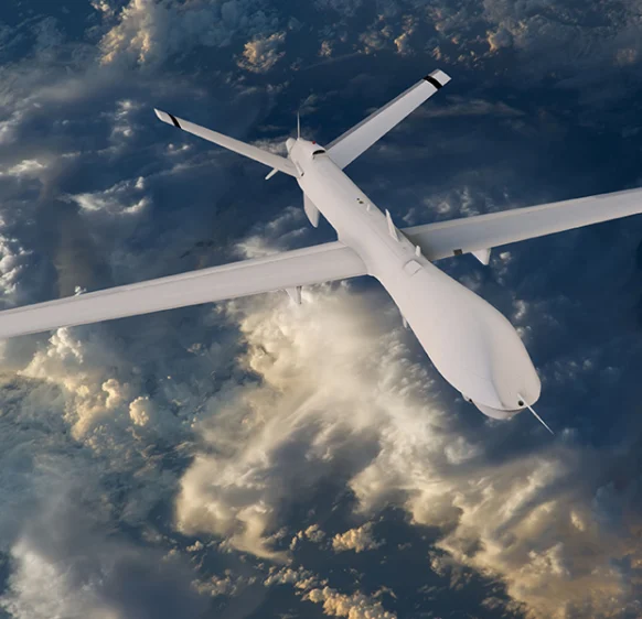
Aerospace
- Aircraft door-lock position detection
- Airlines & Aerospace Our balancing machines and moment weighing scales for aerospace drives ensure maximum precision, ease of use, and modular flexibility delivering reliability and performance without compromise contributing to your economic success.
- Automatic balancing machines Automatic balancing machines from Schenck are advanced solutions for precise balancing of rotating components in automated production processes. We offer systems and stations for balancing crankshafts, wheels and tires, turbochargers, electric armatures, drives, axle drive units, torque converters, drive shafts, disc-shaped rotors, as well as fans. Our systems increase productivity, ensure consistent quality, and are tailored to the needs of the automotive, energy, and industrial sectors.
-
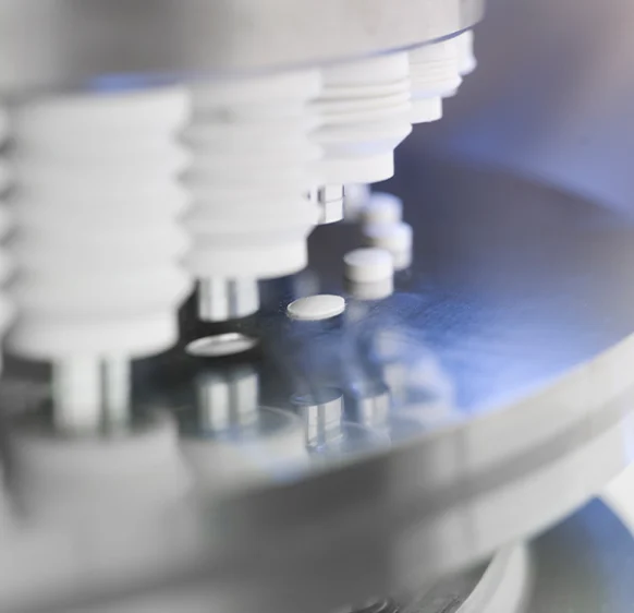
Medical industry
-
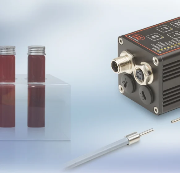
Environment
-
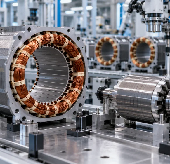
Electric motor manufacturing
-
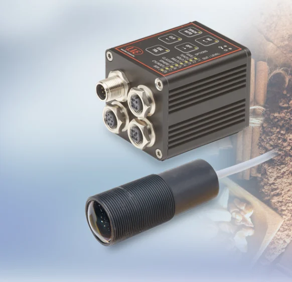
Food industry
-
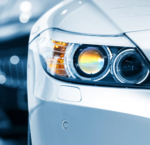
Automotive industry
- Airlines & Aerospace Our balancing machines and moment weighing scales for aerospace drives ensure maximum precision, ease of use, and modular flexibility delivering reliability and performance without compromise contributing to your economic success.
- Automatic balancing machines Automatic balancing machines from Schenck are advanced solutions for precise balancing of rotating components in automated production processes. We offer systems and stations for balancing crankshafts, wheels and tires, turbochargers, electric armatures, drives, axle drive units, torque converters, drive shafts, disc-shaped rotors, as well as fans. Our systems increase productivity, ensure consistent quality, and are tailored to the needs of the automotive, energy, and industrial sectors.
- Axle Drives With our balancing machines for front and rear axle transmissions, the measured unbalance is corrected by drilling into the drive flanges of the transmissions (welding optional). We support you with our interdisciplinary expertise in the production of front and rear axle transmissions from the initial idea to the design stage through to series production.
-
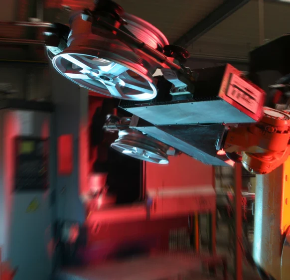
Industrial automation
-
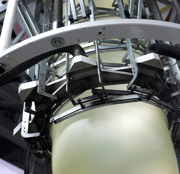
Plastics
-
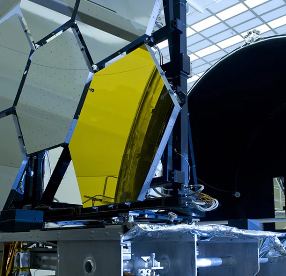
Optics
-
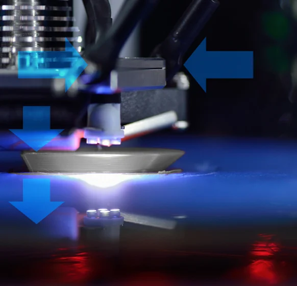
3D printing
-
Battery manufacturing
Frequently asked questions
Answers to the most common questions about our products and services
No. The analog table covers seven ranges from 100 to 1500 mm with P, U or I outputs. The listed digital encoder versions are limited to 1000 and 1500 mm ranges.
CR denotes an integral radial cable for HTL/TTL; SR denotes a radial connector for SSI; BH denotes a bus cover for CANopen, Profibus DP, PROFINET, EtherNet/IP and EtherCAT versions.
Yes. At 1000 mm, HTL/TTL specifies 0.067 mm and SSI or fieldbus 0.012 mm. At 1500 mm, the corresponding values are 0.1 and 0.018 mm.
The IP65 footnote requires the plug to be mated on connector versions. Preserve that condition when selecting the cable and stating protection.
It has an aluminium housing with mounting grooves and specifies −20 to +80°C operation. The wire acceleration limit depends on the selected range.
Get a quote or advice
Tell us what you need and an engineer will come back to you.
Request a quote for this product