
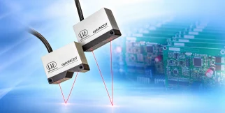
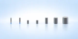
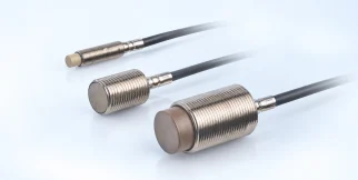
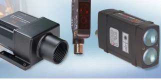
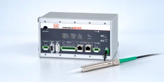
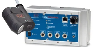
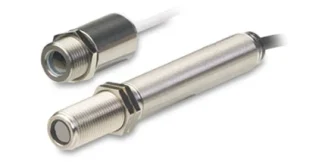
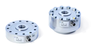
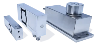
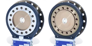
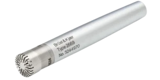
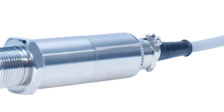



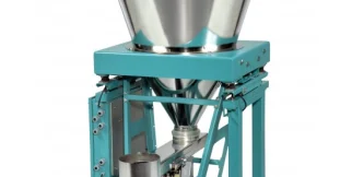

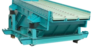
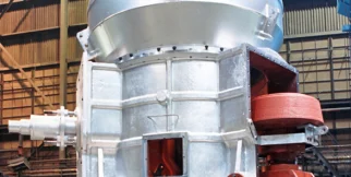
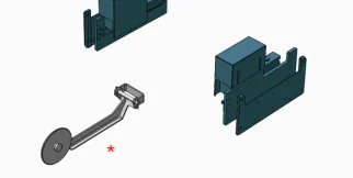
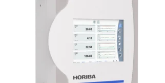
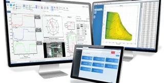
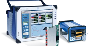
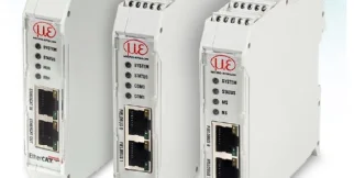
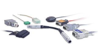
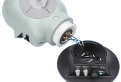
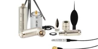
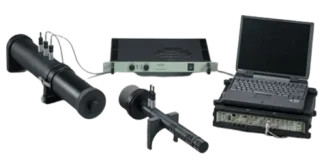
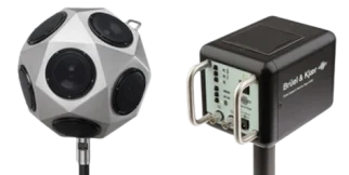
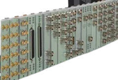
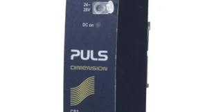
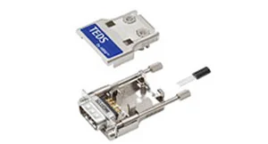
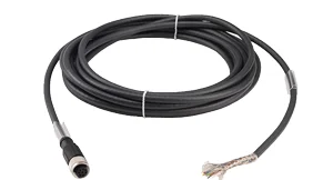
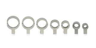
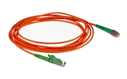
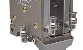

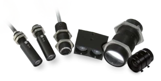










HBK mounting accessories Mounting and mechanical accessories
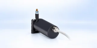
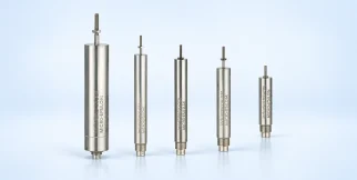
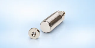
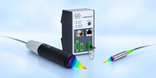
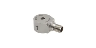
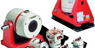
HBK mounting accessories: accessories and system components by HBK for mounting and mechanical accessories.
Visit the HBK site (opens in a new tab)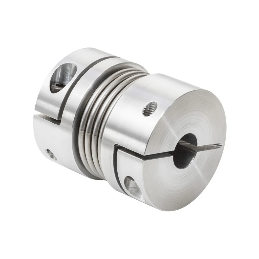
Models in the series
One column per model: what differs between the models of the series.
The industries we serve
-
-
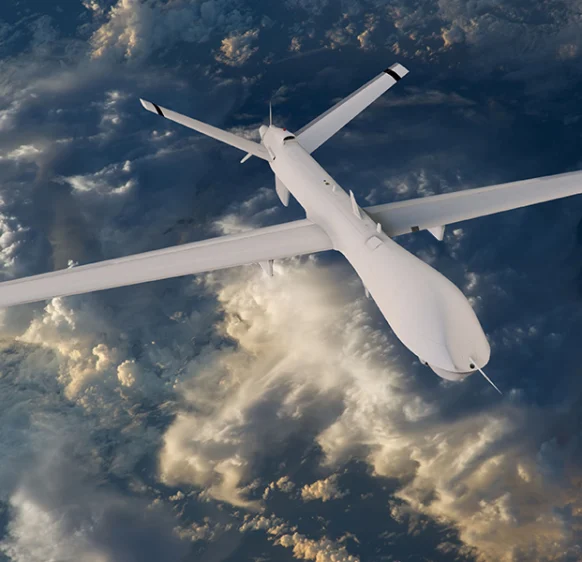
Aerospace
- Aircraft door-lock position detection
- Airlines & Aerospace Our balancing machines and moment weighing scales for aerospace drives ensure maximum precision, ease of use, and modular flexibility delivering reliability and performance without compromise contributing to your economic success.
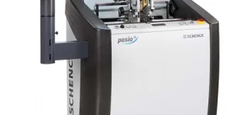
- Automatic balancing machines Automatic balancing machines from Schenck are advanced solutions for precise balancing of rotating components in automated production processes. We offer systems and stations for balancing crankshafts, wheels and tires, turbochargers, electric armatures, drives, axle drive units, torque converters, drive shafts, disc-shaped rotors, as well as fans. Our systems increase productivity, ensure consistent quality, and are tailored to the needs of the automotive, energy, and industrial sectors.
-
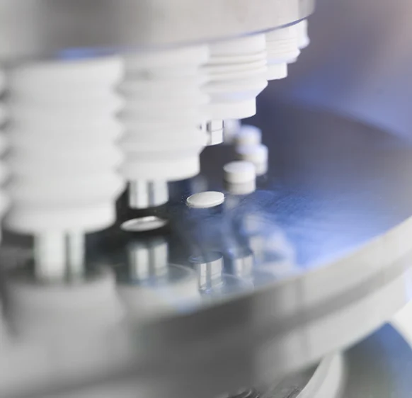
Medical industry
-
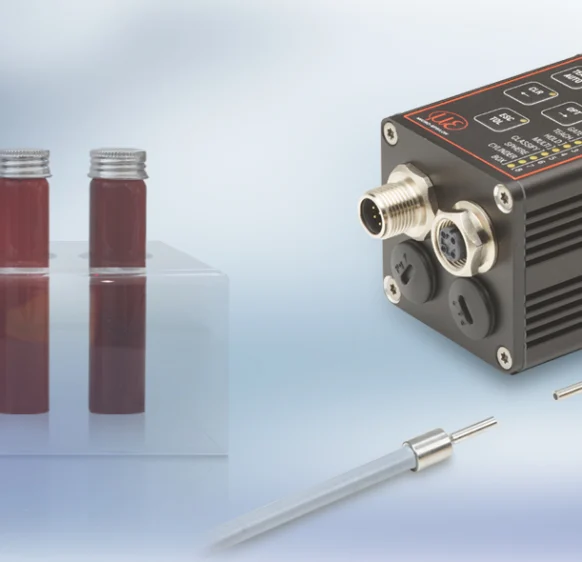
Environment
-
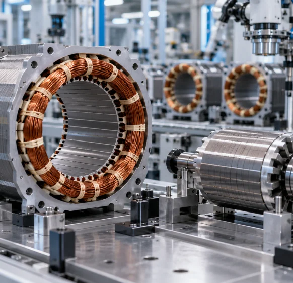
Electric motor manufacturing
-
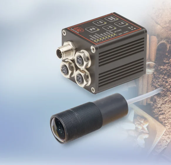
Food industry
-

Automotive industry
- Airlines & Aerospace Our balancing machines and moment weighing scales for aerospace drives ensure maximum precision, ease of use, and modular flexibility delivering reliability and performance without compromise contributing to your economic success.
- Automatic balancing machines Automatic balancing machines from Schenck are advanced solutions for precise balancing of rotating components in automated production processes. We offer systems and stations for balancing crankshafts, wheels and tires, turbochargers, electric armatures, drives, axle drive units, torque converters, drive shafts, disc-shaped rotors, as well as fans. Our systems increase productivity, ensure consistent quality, and are tailored to the needs of the automotive, energy, and industrial sectors.
- Axle Drives With our balancing machines for front and rear axle transmissions, the measured unbalance is corrected by drilling into the drive flanges of the transmissions (welding optional). We support you with our interdisciplinary expertise in the production of front and rear axle transmissions from the initial idea to the design stage through to series production.
-
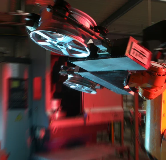
Industrial automation
-
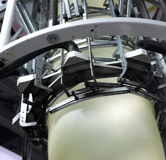
Plastics
-
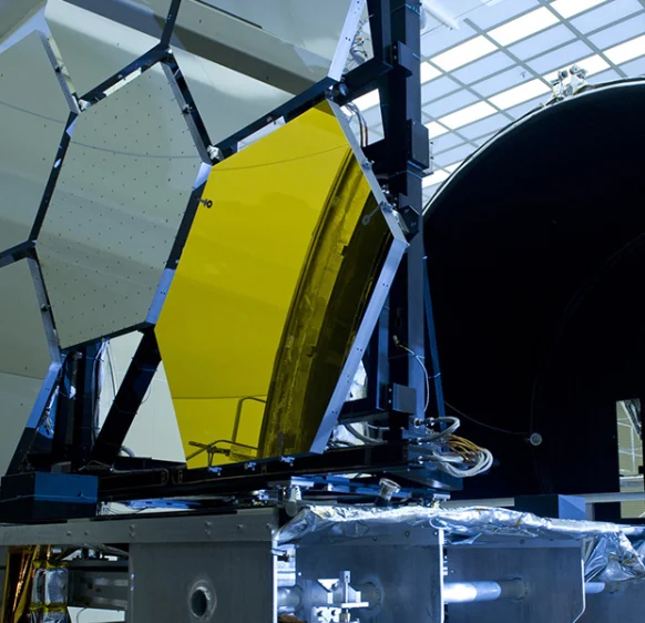
Optics
-
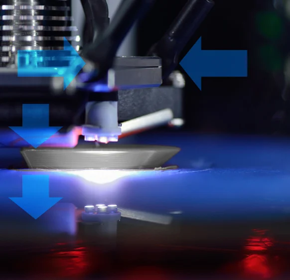
3D printing
-
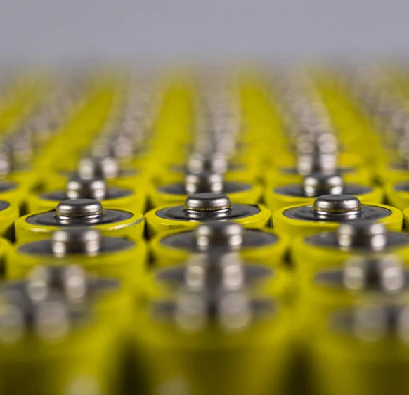
Battery manufacturing
Frequently asked questions
Answers to the most common questions about our products and services
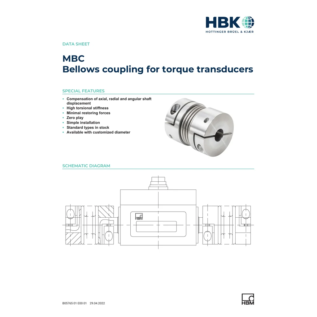
The MBC product data lists compensation for axial, radial, and angular shaft displacement. Permitted values depend on the coupling size and its specification table.
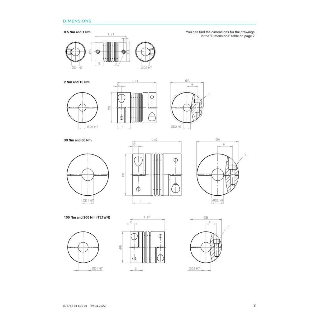
The manufacturer’s table lists T210, T21WN, and T22, depending on rated torque and dimensions. Select the MBC variant for the relevant transducer and range.
The specification lists a maximum speed of 20,000 rpm. Confirm that the selected coupling, transducer, and application also meet their applicable mechanical limits.
MBC product data lists a permissible temperature range of −30 to +120°C. Check transducer and system limits separately.
The installation instructions say not to tighten the coupling bolts until the shafts are mounted in the hubs. They also specify at least a 1 mm gap from the transducer housing unless using the described stop.
Get a quote or advice
Tell us what you need and an engineer will come back to you.
Request a quote for this product