










C10 Force
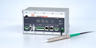
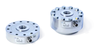
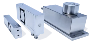
C10: sensors and measurement devices by HBK for force.
This series on the HBK site (opens in a new tab)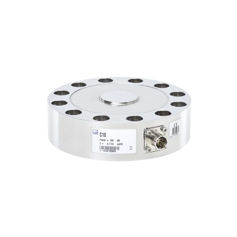
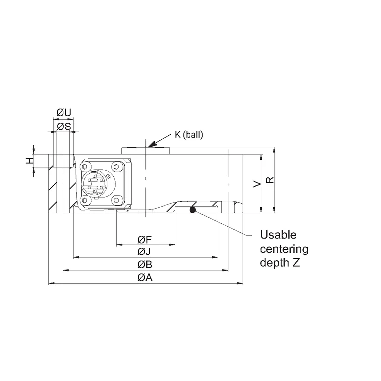
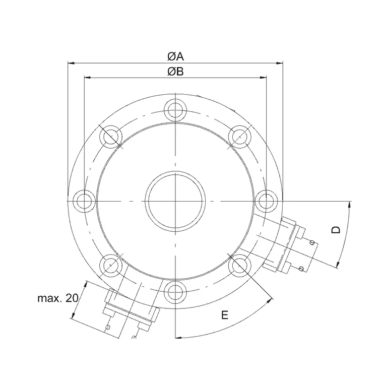
Shared technical specifications for the series
Properties every model in the series has. What differs is in the models table below.
| Ordering options and constraints | K-C10 — capacity: 2.5 kN, 5 kN, 10 kN, 25 kN, 50 kN, 100 kN, 250 kN, 500 kN, 1 MN; bridge: SB, DB; rated_output: N, J; calibration: 50%, 100%; teds: Not selected, T; mechanical_design: W adapter, N flange; plug_protection: P, U; electrical_connection: B, G, K (6 m), V (15 m), 00A4 (VAIO); force_application: O, L; cable_plug: Y, F, Q, N, P, M, X; integrated_amplifier: N, VAIO; constraints: [{"when": {"teds": "T"}, "deny": {"integrated_amplifier": ["VAIO"]}, "reason": "TEDS and the integrated VAIO amplifier are mutually exclusive in the official configuration."}, {"when": {"integrated_amplifier": "VAIO"}, "allow": {"electrical_connection": "00A4 (VAIO)"}, "reason": "The VAIO connection is reserved for the integrated-amplifier option."}] |
|---|
Range across models
The span covered by the models of the series together — not the range of each model.
| Operating temperature | -30–85 °C |
|---|---|
| Protection class (DIN EN 60529) | IP64 |
| Interfaces | IO-Link |
| Force range | 0–50000 N |
| ADC sampling rate | 450–40000 samples/s |
| Nominal force capacity | 2500–1000000 N |
Models in the series
One column per model: what differs between the models of the series.
| Parameter | 1-C10/100KN | 1-C10/10KN | 1-C10/1MN | 1-C10/2.5KN | 1-C10/250KN | 1-C10/25KN | 1-C10/500KN | 1-C10/50KN | 1-C10/5KN | C10-1000kN | C10-100kN | C10-10kN | C10-250kN | C10-25kN | C10-2p5kN | C10-500kN | C10-50kN | C10-5kN | K-C10 · 1 MN | K-C10 · 10 kN | K-C10 · 100 kN | K-C10 · 2.5 kN | K-C10 · 25 kN | K-C10 · 250 kN | K-C10 · 5 kN | K-C10 · 50 kN | K-C10 · 500 kN |
|---|---|---|---|---|---|---|---|---|---|---|---|---|---|---|---|---|---|---|---|---|---|---|---|---|---|---|---|
| Operating temperature | -10–60 °C | -30–85 °C | -10–60 °C | -10–60 °C | -30–85 °C | -10–60 °C | -10–60 °C | -30–85 °C | -30–85 °C | -10–60 °C | -10–60 °C | -10–60 °C | -10–60 °C | -10–60 °C | -30–85 °C | -10–60 °C | -10–60 °C | -10–60 °C | Not specified | Not specified | Not specified | Not specified | Not specified | Not specified | Not specified | Not specified | Not specified |
| Protection class (DIN EN 60529) | IP64 | IP67 | IP64 | IP68 | IP67 | IP64 | IP64 | IP67 | IP67 | IP64 | IP68 | IP64 | IP64 | IP67 | IP68 | IP68 | IP67 | IP68 | Not specified | Not specified | Not specified | Not specified | Not specified | Not specified | Not specified | Not specified | Not specified |
| Interfaces | Not specified | Not specified | Not specified | Not specified | Not specified | Not specified | Not specified | Not specified | Not specified | Ethernet | Ethernet | Ethernet | Ethernet | Ethernet | Ethernet | PROFINET | IO-Link | IO-Link | Not specified | Not specified | Not specified | Not specified | Not specified | Not specified | Not specified | Not specified | Not specified |
| Force range | 0–100000 N | 0–10000 N | 0–1000000 N | 0–2500 N | 0–250000 N | 0–25000 N | 0–500000 N | 0–50000 N | 0–5000 N | 0–1000000 N | 0–100000 N | 0–10000 N | 0–250000 N | 0–25000 N | 0–2500 N | 0–500000 N | 0–50000 N | 0–5000 N | Not specified | Not specified | Not specified | Not specified | Not specified | Not specified | Not specified | Not specified | Not specified |
| Pressure sensor output | mV/V (passive strain gauge) | mV/V (passive strain gauge) | mV/V (passive strain gauge) | mV/V (passive strain gauge) | mV/V (passive strain gauge) | mV/V (passive strain gauge) | mV/V (passive strain gauge) | mV/V (passive strain gauge) | mV/V (passive strain gauge) | Not specified | Not specified | Not specified | Not specified | Not specified | Not specified | Not specified | Not specified | Not specified | Not specified | Not specified | Not specified | Not specified | Not specified | Not specified | Not specified | Not specified | Not specified |
| Sampling rate limited by system readout | True | True | True | True | True | True | True | True | True | Not specified | Not specified | Not specified | Not specified | Not specified | Not specified | Not specified | Not specified | Not specified | Not specified | Not specified | Not specified | Not specified | Not specified | Not specified | Not specified | Not specified | Not specified |
| Outputs and interfaces | Unknown | Unknown | Unknown | Unknown | Unknown | Unknown | Unknown | Unknown | Unknown | Analog 0-10V | Analog 0-10V | Analog 0-10V | Digital I/O | Analog 0-10V | Analog 0-10V | Digital I/O | RS422 / RS485 | Analog 0-10V | Not specified | Not specified | Not specified | Not specified | Not specified | Not specified | Not specified | Not specified | Not specified |
| Repeatability reference | Use the individual calibration certificate and installed-chain verification; no unsupported scalar repeatability is inferred. | Use the individual calibration certificate and installed-chain verification; no unsupported scalar repeatability is inferred. | Use the individual calibration certificate and installed-chain verification; no unsupported scalar repeatability is inferred. | Use the individual calibration certificate and installed-chain verification; no unsupported scalar repeatability is inferred. | Use the individual calibration certificate and installed-chain verification; no unsupported scalar repeatability is inferred. | Use the individual calibration certificate and installed-chain verification; no unsupported scalar repeatability is inferred. | Use the individual calibration certificate and installed-chain verification; no unsupported scalar repeatability is inferred. | Use the individual calibration certificate and installed-chain verification; no unsupported scalar repeatability is inferred. | Use the individual calibration certificate and installed-chain verification; no unsupported scalar repeatability is inferred. | Not specified | Not specified | Not specified | Not specified | Not specified | Not specified | Not specified | Not specified | Not specified | Not specified | Not specified | Not specified | Not specified | Not specified | Not specified | Not specified | Not specified | Not specified |
| Technical specification details | Maximum capacity (nominal load): 22.5 klbf; Output signal: mV/V (passive strain gauge); Height (without accessories): 1.87 in; Diameter (without cable or plug): 6.059043 in | Maximum capacity (nominal load): 2.25 klbf; Output signal: mV/V (passive strain gauge); Height (without accessories): 1.41 in; Diameter (without cable or plug): 4.125976 in | Maximum capacity (nominal load): 225 klbf; Output signal: mV/V (passive strain gauge); Height (without accessories): 3.33 in; Diameter (without cable or plug): 10.98423 in | Maximum capacity (nominal load): 562 lbf; Output signal: mV/V (passive strain gauge); Height (without accessories): 1.41 in; Diameter (without cable or plug): 4.125976 in | Maximum capacity (nominal load): 56.2 klbf; Output signal: mV/V (passive strain gauge); Height (without accessories): 1.87 in; Diameter (without cable or plug): 6.059043 in | Maximum capacity (nominal load): 5.62 klbf; Output signal: mV/V (passive strain gauge); Height (without accessories): 1.41 in; Diameter (without cable or plug): 4.125976 in | Maximum capacity (nominal load): 112 klbf; Output signal: mV/V (passive strain gauge); Height (without accessories): 2.57 in; Diameter (without cable or plug): 7.999984 in | Maximum capacity (nominal load): 11.24 klbf; Output signal: mV/V (passive strain gauge); Height (without accessories): 1.41 in; Diameter (without cable or plug): 4.125976 in | Maximum capacity (nominal load): 1.124 klbf; Output signal: mV/V (passive strain gauge); Height (without accessories): 1.41 in; Diameter (without cable or plug): 4.125976 in | 1000 kN rated capacity = 1,000 kN (101.9716 t mass equivalent at standard gravity); compression | 100 kN rated capacity = 100 kN (10.1972 t mass equivalent at standard gravity); compression | 10 kN rated capacity = 10 kN (1.0197 t mass equivalent at standard gravity); compression | 250 kN rated capacity = 250 kN (25.4929 t mass equivalent at standard gravity); compression | 25 kN rated capacity = 25 kN (2.5493 t mass equivalent at standard gravity); compression | 2.5 kN rated capacity = 2.5 kN (254.9291 kg mass equivalent at standard gravity); compression | 500 kN rated capacity = 500 kN (50.9858 t mass equivalent at standard gravity); compression | 50 kN rated capacity = 50 kN (5.0986 t mass equivalent at standard gravity); compression | 5 kN rated capacity = 5 kN (509.8581 kg mass equivalent at standard gravity); compression | Not specified | Not specified | Not specified | Not specified | Not specified | Not specified | Not specified | Not specified | Not specified |
| Sampling rate reference | The selected HBK conditioner, filter and DAQ determine the digital sample rate. | The selected HBK conditioner, filter and DAQ determine the digital sample rate. | The selected HBK conditioner, filter and DAQ determine the digital sample rate. | The selected HBK conditioner, filter and DAQ determine the digital sample rate. | The selected HBK conditioner, filter and DAQ determine the digital sample rate. | The selected HBK conditioner, filter and DAQ determine the digital sample rate. | The selected HBK conditioner, filter and DAQ determine the digital sample rate. | The selected HBK conditioner, filter and DAQ determine the digital sample rate. | The selected HBK conditioner, filter and DAQ determine the digital sample rate. | MX840B maximum per-channel sample rate; sensor mechanics and filter settings can reduce usable bandwidth | ClipX fixed internal sampling rate; verify the configured filter and usable output bandwidth | DMP41 selectable result rate, intended for reference and calibration measurements | 0.9 ms minimum IO-Link process-data cycle; the sensor electronics sample internally at 40 kHz | 0.9 ms minimum IO-Link process-data cycle; the sensor electronics sample internally at 40 kHz | MX840B maximum per-channel sample rate; sensor mechanics and filter settings can reduce usable bandwidth | MX840B maximum per-channel sample rate; sensor mechanics and filter settings can reduce usable bandwidth | ClipX fixed internal sampling rate; verify the configured filter and usable output bandwidth | DMP41 selectable result rate, intended for reference and calibration measurements | Not specified | Not specified | Not specified | Not specified | Not specified | Not specified | Not specified | Not specified | Not specified |
| Linearity reference | No single accuracy class is inferred when it is not shown for the exact ordering code. | No single accuracy class is inferred when it is not shown for the exact ordering code. | No single accuracy class is inferred when it is not shown for the exact ordering code. | No single accuracy class is inferred when it is not shown for the exact ordering code. | No single accuracy class is inferred when it is not shown for the exact ordering code. | No single accuracy class is inferred when it is not shown for the exact ordering code. | No single accuracy class is inferred when it is not shown for the exact ordering code. | No single accuracy class is inferred when it is not shown for the exact ordering code. | No single accuracy class is inferred when it is not shown for the exact ordering code. | Not specified | Not specified | Not specified | Not specified | Not specified | Not specified | Not specified | Not specified | Not specified | Not specified | Not specified | Not specified | Not specified | Not specified | Not specified | Not specified | Not specified | Not specified |
| Accuracy (% FSO) | Not specified | Not specified | Not specified | Not specified | Not specified | Not specified | Not specified | Not specified | Not specified | 0.02 % | 0.02 % | 0.02 % | 0.02 % | 0.02 % | 0.02 % | 0.02 % | 0.02 % | 0.02 % | Not specified | Not specified | Not specified | Not specified | Not specified | Not specified | Not specified | Not specified | Not specified |
| ADC sampling rate | Not specified | Not specified | Not specified | Not specified | Not specified | Not specified | Not specified | Not specified | Not specified | 40000 samples/s | 450 samples/s | 19200 samples/s | 1111 samples/s | 1111 samples/s | 40000 samples/s | 450 samples/s | 1111 samples/s | 40000 samples/s | Not specified | Not specified | Not specified | Not specified | Not specified | Not specified | Not specified | Not specified | Not specified |
| Selected configuration options | Not specified | Not specified | Not specified | Not specified | Not specified | Not specified | Not specified | Not specified | Not specified | Not specified | Not specified | Not specified | Not specified | Not specified | Not specified | Not specified | Not specified | Not specified | 1 MN nominal force capacity | 10 kN nominal force capacity | 100 kN nominal force capacity | 2.5 kN nominal force capacity | 25 kN nominal force capacity | 250 kN nominal force capacity | 5 kN nominal force capacity | 50 kN nominal force capacity | 500 kN nominal force capacity |
| Nominal force capacity | Not specified | Not specified | Not specified | Not specified | Not specified | Not specified | Not specified | Not specified | Not specified | Not specified | Not specified | Not specified | Not specified | Not specified | Not specified | Not specified | Not specified | Not specified | 1000000 N | 10000 N | 100000 N | 2500 N | 25000 N | 250000 N | 5000 N | 50000 N | 500000 N |
| Status | Active | Active | Active | Active | Active | Active | Active | Active | Active | Active | Active | Active | Active | Active | Active | Active | Active | Active | Active | Active | Active | Active | Active | Active | Active | Active | Active |
| Datasheet | PDF — K-C10 · 1 MN (opens in a new tab) | PDF — K-C10 · 10 kN (opens in a new tab) | PDF — K-C10 · 100 kN (opens in a new tab) | PDF — K-C10 · 2.5 kN (opens in a new tab) | PDF — K-C10 · 25 kN (opens in a new tab) | PDF — K-C10 · 250 kN (opens in a new tab) | PDF — K-C10 · 5 kN (opens in a new tab) | PDF — K-C10 · 50 kN (opens in a new tab) | PDF — K-C10 · 500 kN (opens in a new tab) |
Compatible accessories
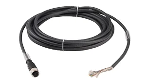
Cables
-
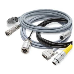 K-CAB-F-B
Only for source configuration configuration-1c8a51fe4b0759651da3bc38: K-C10 · 1 MN configuration; selected configuration must be matched before display.; Only for the listed passive SG sensor socket; fixed-cable K/V and VAIO/4-pin IO-Link are excluded. Select the amplifier end and validate carrier-frequency precision, EMC and calibration with the cable length.; 0131: static/dynamic bend radius 22/50 mm, -50…80 °C, 280 Ω/km; high-precision use may require low carrier frequency and stable temperature. 0157: 37/75 mm, -50…85 °C, 78 Ω/km. 139B: 75 mm static, no drag chain; -30…70 °C stationary / -5…50 °C moving; incompatible with P/M ends.; IP protection depends on the actual sensor socket, seal and connector locking; a generic connector IP rating is not the assembled sensor IP rating.
-
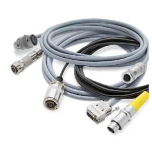 K-CAB-F-G
Only for source configuration configuration-1c8a51fe4b0759651da3bc38: K-C10 · 1 MN configuration; selected configuration must be matched before display.; Only for the listed passive SG sensor socket; fixed-cable K/V and VAIO/4-pin IO-Link are excluded. Select the amplifier end and validate carrier-frequency precision, EMC and calibration with the cable length.; 0131: static/dynamic bend radius 22/50 mm, -50…80 °C, 280 Ω/km; high-precision use may require low carrier frequency and stable temperature. 0157: 37/75 mm, -50…85 °C, 78 Ω/km. 139B: 75 mm static, no drag chain; -30…70 °C stationary / -5…50 °C moving; incompatible with P/M ends.; IP protection depends on the actual sensor socket, seal and connector locking; a generic connector IP rating is not the assembled sensor IP rating.
-
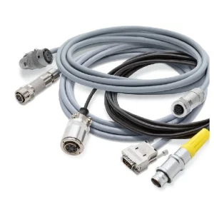 K-CAB-F-L
Only for source configuration configuration-1c8a51fe4b0759651da3bc38: K-C10 · 1 MN configuration; selected configuration must be matched before display.; Only for the listed passive SG sensor socket; fixed-cable K/V and VAIO/4-pin IO-Link are excluded. Select the amplifier end and validate carrier-frequency precision, EMC and calibration with the cable length.; 0131: static/dynamic bend radius 22/50 mm, -50…80 °C, 280 Ω/km; high-precision use may require low carrier frequency and stable temperature. 0157: 37/75 mm, -50…85 °C, 78 Ω/km. 139B: 75 mm static, no drag chain; -30…70 °C stationary / -5…50 °C moving; incompatible with P/M ends.; IP protection depends on the actual sensor socket, seal and connector locking; a generic connector IP rating is not the assembled sensor IP rating.
-
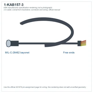 1-KAB157-3
Only for source configuration configuration-1c8a51fe4b0759651da3bc38: K-C10 · 1 MN configuration; selected configuration must be matched before display.; The threaded cable is rated differently in U10M and C10 documents; do not assign a universal IP class. Check socket, locked connector and end wiring.
-
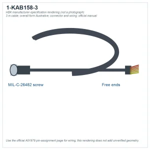 1-KAB158-3
Only for source configuration configuration-1c8a51fe4b0759651da3bc38: K-C10 · 1 MN configuration; selected configuration must be matched before display.; The threaded cable is rated differently in U10M and C10 documents; do not assign a universal IP class. Check socket, locked connector and end wiring.
-
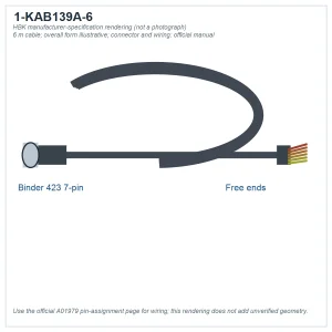 1-CON/BS1
Only for source configuration configuration-1c8a51fe4b0759651da3bc38: K-C10 · 1 MN configuration; selected configuration must be matched before display.; BS1: cable Ø4–6.5 mm; BS2: Ø≥6.5 mm. Match bayonet/threaded sensor connection, sealing and wiring.
-
1-CON/BS2
Only for source configuration configuration-1c8a51fe4b0759651da3bc38: K-C10 · 1 MN configuration; selected configuration must be matched before display.; BS1: cable Ø4–6.5 mm; BS2: Ø≥6.5 mm. Match bayonet/threaded sensor connection, sealing and wiring.
-
3-3312.0354
Only for source configuration configuration-1c8a51fe4b0759651da3bc38: K-C10 · 1 MN configuration; selected configuration must be matched before display.; BS1: cable Ø4–6.5 mm; BS2: Ø≥6.5 mm. Match bayonet/threaded sensor connection, sealing and wiring.
Mounting
-
 1-EDO3/50KN
Only for source configuration configuration-55a98f99bd0d0593c2edc147: K-C10 · 50 kN configuration; selected configuration must be matched before display.; Match nominal capacity, contact geometry and installation; not a tension eye.
-
1-EDO3/100KN
Only for source configuration configuration-09c47c76ba2210f2dd3cf0cf: K-C10 · 250 kN configuration; selected configuration must be matched before display.; Match nominal capacity, contact geometry and installation; not a tension eye.
-
1-EDO3/500KN
Only for source configuration configuration-a27443e334e84d66dbb0b61b: K-C10 · 500 kN configuration; selected configuration must be matched before display.; Match nominal capacity, contact geometry and installation; not a tension eye.
-
1-EDO3/1MN
Only for source configuration configuration-1c8a51fe4b0759651da3bc38: K-C10 · 1 MN configuration; selected configuration must be matched before display.; Match nominal capacity, contact geometry and installation; not a tension eye.
The industries we serve
-
-
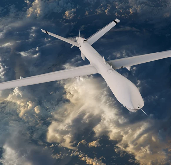
Aerospace
- Aircraft door-lock position detection
- Airlines & Aerospace Our balancing machines and moment weighing scales for aerospace drives ensure maximum precision, ease of use, and modular flexibility delivering reliability and performance without compromise contributing to your economic success.
- Automatic balancing machines Automatic balancing machines from Schenck are advanced solutions for precise balancing of rotating components in automated production processes. We offer systems and stations for balancing crankshafts, wheels and tires, turbochargers, electric armatures, drives, axle drive units, torque converters, drive shafts, disc-shaped rotors, as well as fans. Our systems increase productivity, ensure consistent quality, and are tailored to the needs of the automotive, energy, and industrial sectors.
-
Medical industry
-
Environment
-
Electric motor manufacturing
-
Food industry
-
Automotive industry
- Airlines & Aerospace Our balancing machines and moment weighing scales for aerospace drives ensure maximum precision, ease of use, and modular flexibility delivering reliability and performance without compromise contributing to your economic success.
- Automatic balancing machines Automatic balancing machines from Schenck are advanced solutions for precise balancing of rotating components in automated production processes. We offer systems and stations for balancing crankshafts, wheels and tires, turbochargers, electric armatures, drives, axle drive units, torque converters, drive shafts, disc-shaped rotors, as well as fans. Our systems increase productivity, ensure consistent quality, and are tailored to the needs of the automotive, energy, and industrial sectors.
- Axle Drives With our balancing machines for front and rear axle transmissions, the measured unbalance is corrected by drilling into the drive flanges of the transmissions (welding optional). We support you with our interdisciplinary expertise in the production of front and rear axle transmissions from the initial idea to the design stage through to series production.
-
Industrial automation
-
Plastics
-
Optics
-
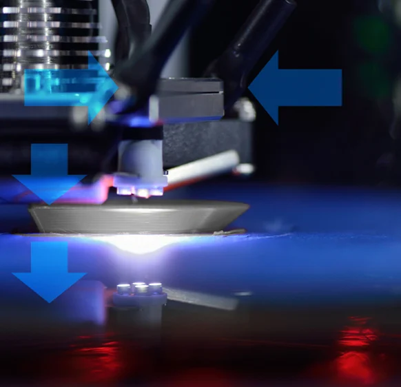
3D printing
-
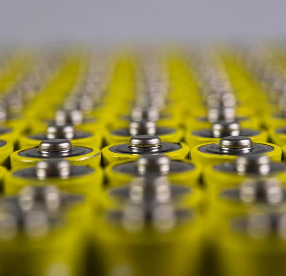
Battery manufacturing
Frequently asked questions
Answers to the most common questions about our products and services
C10 is designed to measure compressive force. Select another transducer when tensile-force measurement is required.
No. The datasheet qualifies IP68 by the fixed-cable option and nominal force of at least 25 kN. Check the selected configuration.
It provides two electrically isolated measuring bridges in one sensing body for connection to separate amplifiers.
C10 offers different connector and cable options. Match the connection code to the amplifier and required protection.
Some C10 models have a rated output above 4 mV/V; the improvement description specifies this from 25 kN capacity. Select a bridge input and excitation matching the actual model sensitivity to avoid clipping; do not apply one value to every capacity.
Get a quote or advice
Tell us what you need and an engineer will come back to you.
Request a quote for this product